
Actual Step |
Polar Alignment using iPolar |
Updated: 2023-08-03 |
Previous Step |
||
Next Step |
||
|
Required Equipment |
|
|
Hardware |
iEQ45 Pro Gear, Windows Laptop |
|
Software |
|
- Adjusting the Equatorial Mount Pointing Direction (Zero Position)

- Place the counterweight shaft at the lowest point.
- Adjust the altitude to your latitude.
- Roughly point the mount to the North (or South if you are in the southern hemisphere).
Important: You do not see the North Star (or Polaris), but your mount should
roughly point in the direction of Polaris (in the northern hemisphere)
> see also Masking Objects later in this chapter - Check GPS: Make sure iOptron Commander is running and shows GPS = OK
- Connect iPolar in software
- Run iOptron Commander
- Run iPolar Software (3339_iOptron_iPolar.exe)
- Click on “Connect” button to connect the iPolar to the computer.
- Take a dark frame
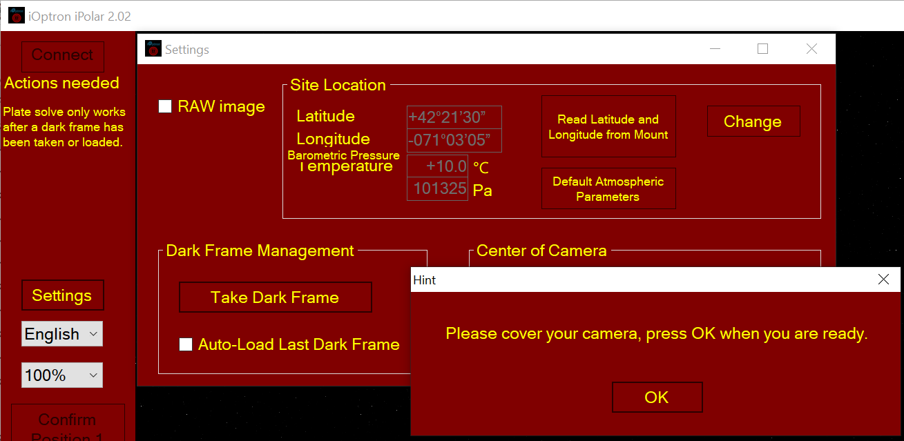
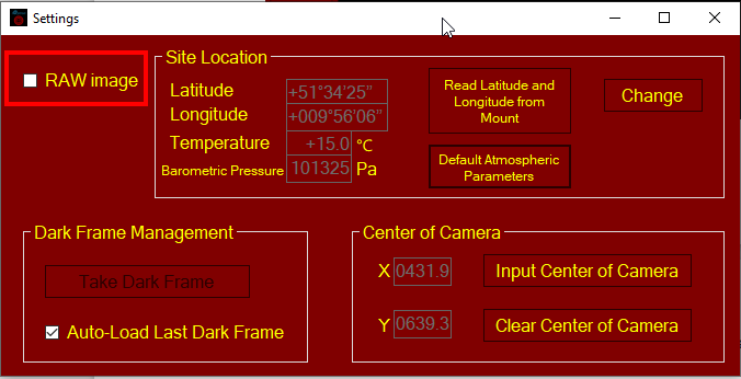
- Set Location and Atmospheric Parameters
Read location information from an ASCOM supported iOptron Mount.
NOTE: You’ll need the latest firmware and iOptron Commander, as well as .NET 4.8 and above. Make sure the mount is connected to the computer via ASCOM. - Click on Settings
- Click on Read Location from Mounts
- Calibrating the iPolar Camera
The calibration process tells the software if the iPolar is aligned to the mount RA axis of the mount after installation. Calibration is only required when:
- iPolar is being used for the first time;
- iPolar is not well aligned (removed, rotated, etc.); or
- You are suspect that the alignment is off.
NOTE: You may need to click on Clear Center of Camera in order to perform a new calibration.
- iPolar Rotation with Mount RA Axis
For most EQ mounts, the iPolar can be rotated with the RA axis. - The camera center of the iPolar/RA axis can be determined with two single positions that separated by 45 degrees or more.
- Start the RA axis of the mount from the first position and click on Confirm Position 1.
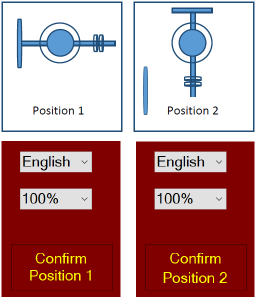
- Rotate the RA axis more than 45 degrees and click on Confirm Position 2. The start and end positions can be arbitrary.
- Plate Solving and Polar Alignment
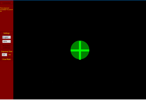
Once iPolar has been calibrated, a bright red cross appears on the screen representing the polar scope camera center/mount RA axis. The alignment software will perform plate solving in the vicinity of the pole star area. It is not necessary to see the pole star. The camera will take the images, enhance the stars and darken the background, remove the noise and plate solve the area. It will show the pole with a dark RED DOT. If there are not enough stars, or there are too many stars, you can adjust the exposure time and/or gain to make sure that at least 4 stars can be detected. Adjust the elevation and azimuth knobs to move the RED DOT toward the RED CROSS. The image will be enlarged as they move closer.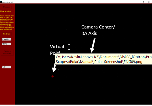
- When the RED DOT completely covers the RED CROSS, the pole alignment is complete.
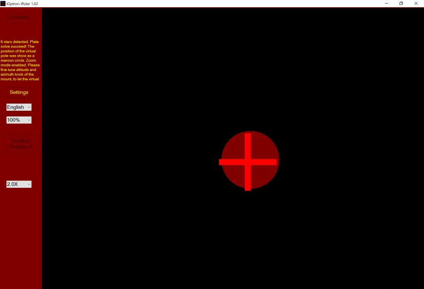
- When the circle overlaps the cross, they turn green and the polar alignment is complete.
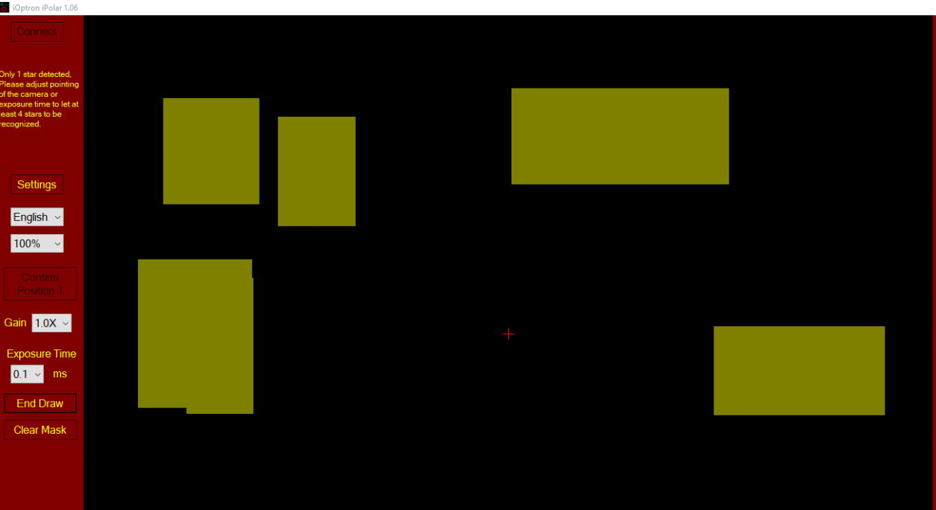
- Masking objects
If there are some tree branches or part of the building get in front of the iPolar camera (click on Settings=>RAW image to check), you can use the Draw Mask function to hide that part from the plate solving: - Uncheck RAW Image in Settings
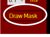
- Click on Draw Mask
- Move the mouse cursor to the beginning corner of the area you want to ignore, click the mouse button.
- Move to the last corner and click the mouse. A green rectangle will appear on the screen.
- Select a different area if necessary.
- Click on END Draw to confirm, or click Clear Mask to clear all the masks.
Next step: Star Alignment
Reference:
[1] iOptron: 3339_iPolarOperationManual.pdf
Created with the Personal Edition of HelpNDoc: Make Your PDFs More Secure with Encryption and Password Protection