Preparation

- Warning:
- It is recommended that one of the collimation screws (e.g. the "Y" screw) be maintained in its current state, thus maintaining the mirror in its current position and changes in mirror spacing are avoided.
- It is also recommended not to touch the central locking screw on the second mirror, as this can cause the mirror to be completely out of alignment.
- In contrast to the note on the picture above, it is sometimes necessary to slightly loosen the central screw with a Philips screwdriver in order to tighten the X and Z screws - please only do this very carefully and then immediately retighten the X or Z screw to be tightened again (clockwise rotation).
- However, it is always safer to loosen only one of the locking screws to allow the other two to move freely
|
M42 x 0.75 female threads are located on OCAL after opening the top cover. We recommend the following methods for Initial OCAL Setup
- If your focuser has an M42 x 0.75 male thread, simply screw OCAL directly onto the thread on the focuser directly.
- If there is no thread at the end of the focuser and it uses a compression ring or screw fixed brass ring, please use some kind of extension adapter, such as 2-inch to m42, screw OCAL to the coupling threads of the coma corrector lens, and insert the coma corrector lens directly into the focuser. This method will achieve more precise collimation, but it will cause the image to be blurred.
- If possible remove the internal baffle on the main mirror that blocks obliquely incident light (this is possible e.g. on the TSO 203/1624 RC PRO)
- Use a lightpad or a backlit white sheet of paper in front of the telescope to make the details inside the telescope visible.
- Move the focuser to a position where the distance to the sensor plane is similar to the distance to the surface of the OCAL camera (e.g., 9200 EAF steps / 27 mm), as this affects the the calibration.
- Carefully loosen 2 of the 3 locking screws on the primary mirror (e.g. screws X and Z) using a 2.5mm Allen key, but under no circumstances loosen the 3rd screw Y, in order to prevent the mirror from shifting laterally.
- Place a flashlight inside the telescope and point it at the OCAL camera so that the red center mark on the OCAL camera is more clearly visible.
Please choose according to your own situation.
|
Enter Calibration Code

|
- Each OCAL collimator has a center calibration code. First look for the printed serial number on the back side of your OCAL camera (e.g. SN = 1B1716)
- Download the actual OCAL center calibration codes OCAL2.0 Center Calibration Code.xlsx or goto the OCAL page: http://www.ocalworld.com/EN/software-download.html to locate your calibration code file.
- Open the excel file and search for your OCAL SN number
- Locate and open the focus.txt file in the OCAL installation folder: (in my case, it's on: drive:\Kits\astro\Collimation\Ocal)
- Paste the Center Calibration Code (0 0 1620.35 1247.94) into your focus.txt file. Save it.
|
Start the OCAL App
|
- activate the camera ("Turn on Camera")
- Click "Camera Control". Try to adjust Focus and Exposure to suitable value.
|
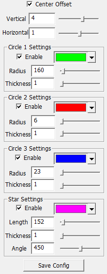
Initial OCAL Settings
|
Setting example: these settings apply to my TSO 203/1624 RC PRO carbon telescope.
Remember to save the settings after you finish the collimation.
|
Center Offset Function
Before correction of the center offset:

After correction of the center offset:

|
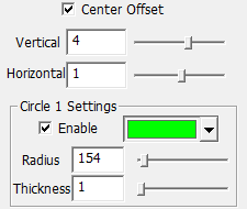
Activate the green circle
Due to manufacturing and telescope adapter tolerances, the OCAL program reticule may not be perfectly centered; we use the Center Offset function to make a slight adjustment.
Procedure:
The adjustment method is very simple. For RC telescopes, use the outer edge of the primary mirror (A) and align the green circle with it.
IMPORTANT NOTE FOR ALL SUBSEQUENT STEPS:
If the green circle has moved out of the center after adjusting the mirror, always recenter the circles by keeping the green circle on the outer edge of the primary mirror!
Inital Center Settings
Then use it as a reference to adjust the offset value (Save Config).
|
|

|
Misaligned Secondary Mirror
This image shows the initial collimation state of the telescope. Both mirrors are currently out of alignment.
The aim of this step is to bring the small black dot (this is the reflection of the OCAL camera lens) exactly into the center of the red area. The red area in turn is the reflection of the OCAL camera housing. In order to see this clearly, sufficient light must fall into the telescope from the front. This is best achieved by placing a piece of white paper in front of the telescope at a distance of 10 cm so that the collimation screws of the secondary mirror can still be easily reached, and illuminating this paper screen from behind.
Procedure:
- Use the 4mm Allen wrench on the 2 push/pull adjustment screws X and Z of the secondary mirror to move the black spot to the center.
- When finished , carefully retighten the center screw if necessary.
- It is recommended that the "Y" screw be maintained in its current state, thus maintaining the mirror in its current position and changes in mirror spacing are avoided.
- In contrast to the note on the left-hand picture, it is sometimes necessary to slightly loosen the central screw in order to tighten the X and Z screws (by a clockwise rotation) - please only do this very carefully and then immediately retighten the X or Z screw to be tightened again (clockwise rotation).
|
|

|
Well Aligned Secondary Mirror
When the adjustment is complete, the black dot should be right in the center of the dark circle of the 2nd mirror center mark.
IMPORTANT: If, after adjusting the mirror, the green, blue or red circles have moved out of the center, as in this picture, always recenter the circles by keeping the green circle on the outer edge of the primary mirror! Use the Center Offset settings to re-center the circles.
|
Finalization
|
When finished, carefully try to retighten the center screw if necessary. Check that the mirror is still in place.
|
Next Step
|
Step 4: Adjusting the Primary Mirror
|