
Actual Step |
Step 2: Check and Correct the Mirror Spacing |
updated: 2024-11-06 |
|
Purpose |
Check and correct the distance between the primary and secondary mirrors to set the system to the correct focal length (and backfocus). |
|
|
Previous Step |
||
|
Next Step |
After correcting the mirror distance, the primary mirror must be realigned: |
|
The mirror distance, also known as the separation between the primary and secondary mirrors, plays a crucial role in the optical performance of a Ritchey-Chrétien telescope. An incorrect mirror distance can have several effects on the image quality:
- Focal Length Abberations: The mirror distance is critical to the focal length and back focus of your telescope:
- reducing the mirror distance will increase the focal length and the backfocus
- while increasing the distance will decrease both parameters
This adjustment allows for fine-tuning the telescope's focus and optical performance.
WARNING:
- never rely on the manufacturer's focal length specification - this value is not exactly the same for most telescopes of the same production line due to manufacturing tolerances and can vary by up to 1%.
- The better parameter to achieve is the back focus, which is set at 254 mm for this telescope. This Backfocus Method is explained later in this chapter.
- Spherical Aberration: If the mirror distance is not set correctly, it can introduce spherical aberration into the optical system. Spherical aberration causes different parts of the image to be focused at different distances from the optical axis, resulting in a blurred or distorted image.
- Astigmatism: Incorrect mirror distance can also lead to astigmatism, where light rays from a point source are not focused to a single point, but rather to two different focal lines. This can cause the image to appear elongated or distorted.
- Coma: Coma is another optical aberration that can occur when the mirror distance is incorrect. Coma causes off-axis points of light to appear distorted, with comet-like tails. This aberration can significantly degrade image quality, especially in wide-field observations.
- Field Curvature: Improper mirror distance can lead to field curvature, where the focal plane of the telescope is curved rather than flat. This can result in the edges of the field of view being out of focus compared to the center, reducing overall image sharpness.
- Collimation Issues: Incorrect mirror distance can make it challenging to achieve proper collimation (alignment) of the telescope's optics. Poor collimation can further exacerbate optical aberrations and reduce image quality.
The relationship between the focal length and the mirror distance in a RC telescopes is not linear. It follows complex optical formulas based on the design parameters of the telescope, including the curvature and separation of the primary and secondary mirrors.
- The smaller the mirror distance, the greater the focal length or backfocus, and vice versa.
Corrective action
- If the measured backfocus is less than nominal, the mirror distance is too large:
- In this case, the collimation screws X, Y, Z must be turned clockwise to reduce the mirror distance.
- - If the measured back focus is greater than the nominal value, the mirror distance is too short:
- In this case, the collimation screws X, Y, Z must be turned counterclockwise to increase the mirror distance.
Example:
Supposedly the Distance Factor (Delta D / Delta F) for the TS1624rtASI294 telescope is said to be 1:6, i.e. to increase the focal length or backfocus by 1mm, the mirror distance must be reduced by 0.1667 mm.
WARNING: The distance factor of 6 has been found somewhere on the Internet and has not yet been confirmed.
Checking the Mirror Distance
Since the mirror spacing is usually not disclosed by the manufacturer, there are 3 ways to detect such a mirror spacing error:
- Ronchi Eypiece
If you center the telescope on a star of magnitude 2 (like Polaris) and use a Ronchi Eypiece, you can already gain initial indications of an incorrect mirror distance. The focuser must be set slightly intrafocal (i.e. too short). Then the following images become visible in the eyepiece: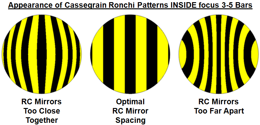
- RC mirrors to close together: instrument is undercorrected
- RC mirrors too far apart: instrument is overcorrected
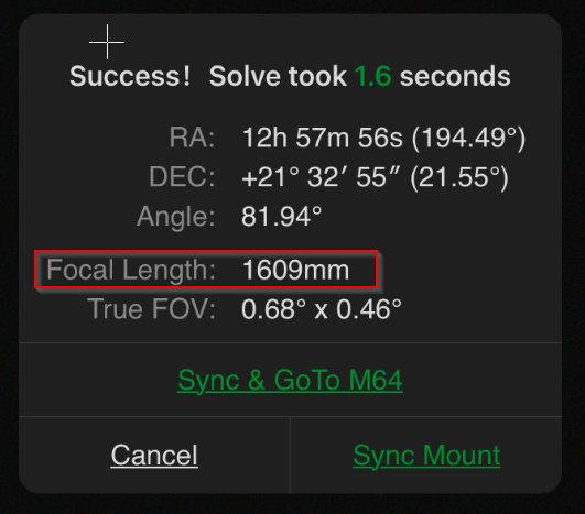
- Plate Solving Method: a mirror distance error can be determined from an image taken with the collimated telescope by subsequently subjecting the image to a plate resolution. With a suitable plate solving, the focal length of the telescope can also be determined.
- use of the ASIAIR plate solve function during the night time exposure / collimation session:
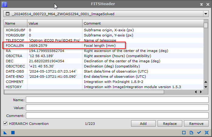
- using PixInsight during the post processing steps: (Process > Image > FITS Header):
- using F4W2HDU
- using AllSky Plate Solver (requires FIT images)
- Astrometry.net
- or some other plate solver
Result: In this case, the telescope has a nominal focal length of 1624 mm, but the image shows a focal length of only 1602.36 mm. The focal length error is therefore
1609 - 1624 = -15 mm too short!! => (error: 0.92%)
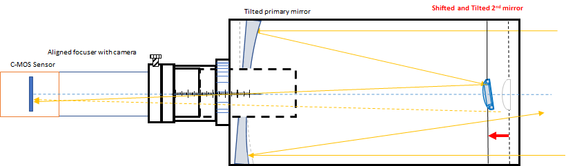
- by measuring the distance between the backside of the telescope (without focuser) and the position of the focal point plane (surface of the CMOS sensor). This can be done, for example, with a digital caliper or by taking into account the number of steps of the EAF at the time of maximum sharpness of an image of a star. Only the variable part of the focuser needs to be taken into account, as all other optical components such as tube extensions, adapters, extension rings, the fixed part of the focuser, the position of the CMOS sensor within the camera etc. always have the same fixed length.
- E.g. using the optical configuration TS1624rtASI294 consisting of a TSO RC 203/1624 Telescope with a 2,5" rack and pinion focuser, rotators, adapters and a ZWO ASI294MC Pro camera, the fixed optical length of all components between the telescope and the CMOS-Sensor sum up to:
E (extensions) + 65.00 mm
F (Focuser Fixed dist.): + 84.50 mm
T (Camera Tail): + 75.10 mm
Lfix = 224.60 mm
The difference between the nominal backfocus and the fixed length of the optical components Lfix therefore corresponds exactly to the length of the variable part of the focuser by which it must be extended (nominal distance):
Backfocus 254.00 mm
./. Lfix - 224.60 mm
V variable Focuser distance + 29.40 mm
or EAF position 10212 steps
Using the EAF stepsize of 0.00288 mm/step:
For example, if you measured 10373 steps instead of 10212 steps for the ideal focus, the variable focuser length V is equal to:
V = 10374 * 0.00288 mm/step => 29.88 mm
Lfix + 224.60 mm
measured variable Focuser part + 29.88 mm
Measured Backfocus = 254.48 mm
Nominal Backfocus - 254.00 mm
Backfocus difference + 0.49 mm too long
Ideally, both approaches aa) and ab) should return the same result.
If they do not match, it is due to the inaccuracy of the focuser's drive system (e.g. backslash).
- Real Star Method (probably the most accurate approach): Target a star field with some brighter stars during the night time and then bring the focuser into the ideal position to bring the sensor to the given backfocus position (e.g. 254 mm) from the back of the tube, either by measuring the backfocus with a digital caliper or by entering the estimated EAF Focuser steps for the actual optical configuration in the ASIAIR , point the telescope to a star field and adjust the secondary until you are in focus.
Links:
Created with the Personal Edition of HelpNDoc: Easily Add Encryption and Password Protection to Your PDFs